Storage system redundant array of solid state disk array

a storage system and array technology, applied in the direction of error detection/correction, input/output to record carriers, instruments, etc., can solve the problems of ssds associated with the parity segments wearing more often than the rest of the drives, and changes to any of the blocks within the segment will increase the overhead associated with gc substantially

Inactive Publication Date: 2015-07-30
AVALANCHE TECH
View PDF1 Cites 43 Cited by
  • Summary
  • Abstract
  • Description
  • Claims
  • Application Information

AI Technical Summary

Benefits of technology

[0004]Briefly, a storage system includes a storage processor coupled to a plurality of solid state disks (SSDs) and a host, the plurality of SSDs being identified by SSD logical block addresses (SLBAs). The storage processor receives a command from the host to write data to the plurality of SSDs, the command from the host accompanied by information used to identify a location within the plurality of SSDs to write the data, the identified location referred to as a host LBA. The storage processor includes a central processor unit (CPU) subsystem and maintains unassigned SLBAs of a corresponding SSD. CPU subsystem upon receiving the co...

Problems solved by technology

Achieving high and/or consistent performance in systems such as computer servers (or servers in general) or storage servers (also known as “storage appliances”) that have one or more logically-addressed SSDs (laSSDs) has been a challenge.
As such...

Method used

View more

Image

Smart Image Click on the blue labels to locate them in the text.
Viewing Examples
Smart Image
  • Storage system redundant array of solid state disk array
  • Storage system redundant array of solid state disk array
  • Storage system redundant array of solid state disk array

Examples

Experimental program
Comparison scheme
Effect test

Embodiment Construction

[0018]In the following description of the embodiments, reference is made to the accompanying drawings that form a part hereof, and in which is shown by way of illustration of the specific embodiments in which the invention may be practiced. It is to be understood that other embodiments may be utilized because structural changes may be made without departing from the scope of the present invention. It should be noted that the figures discussed herein are not drawn to scale and thicknesses of lines are not indicative of actual sizes.

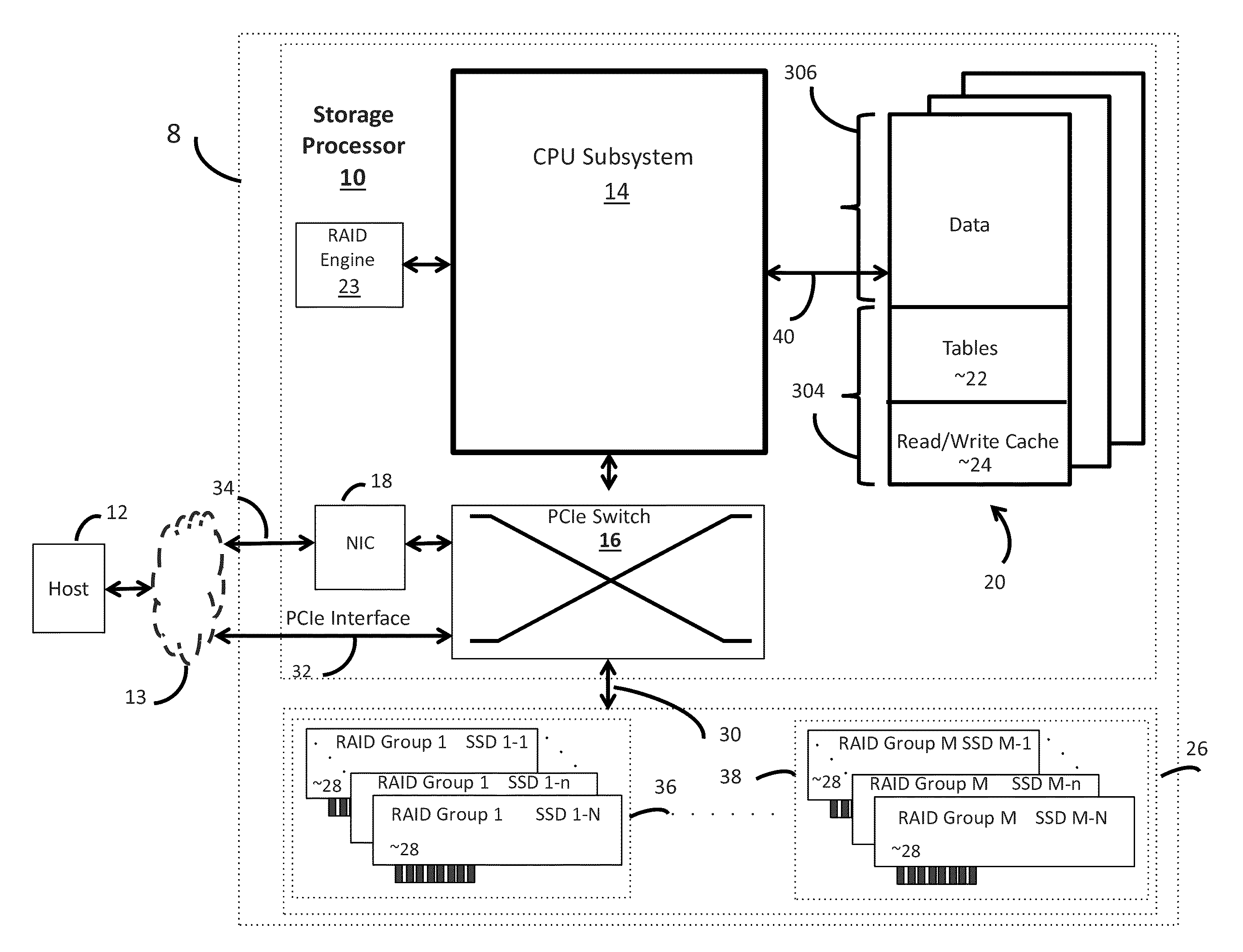
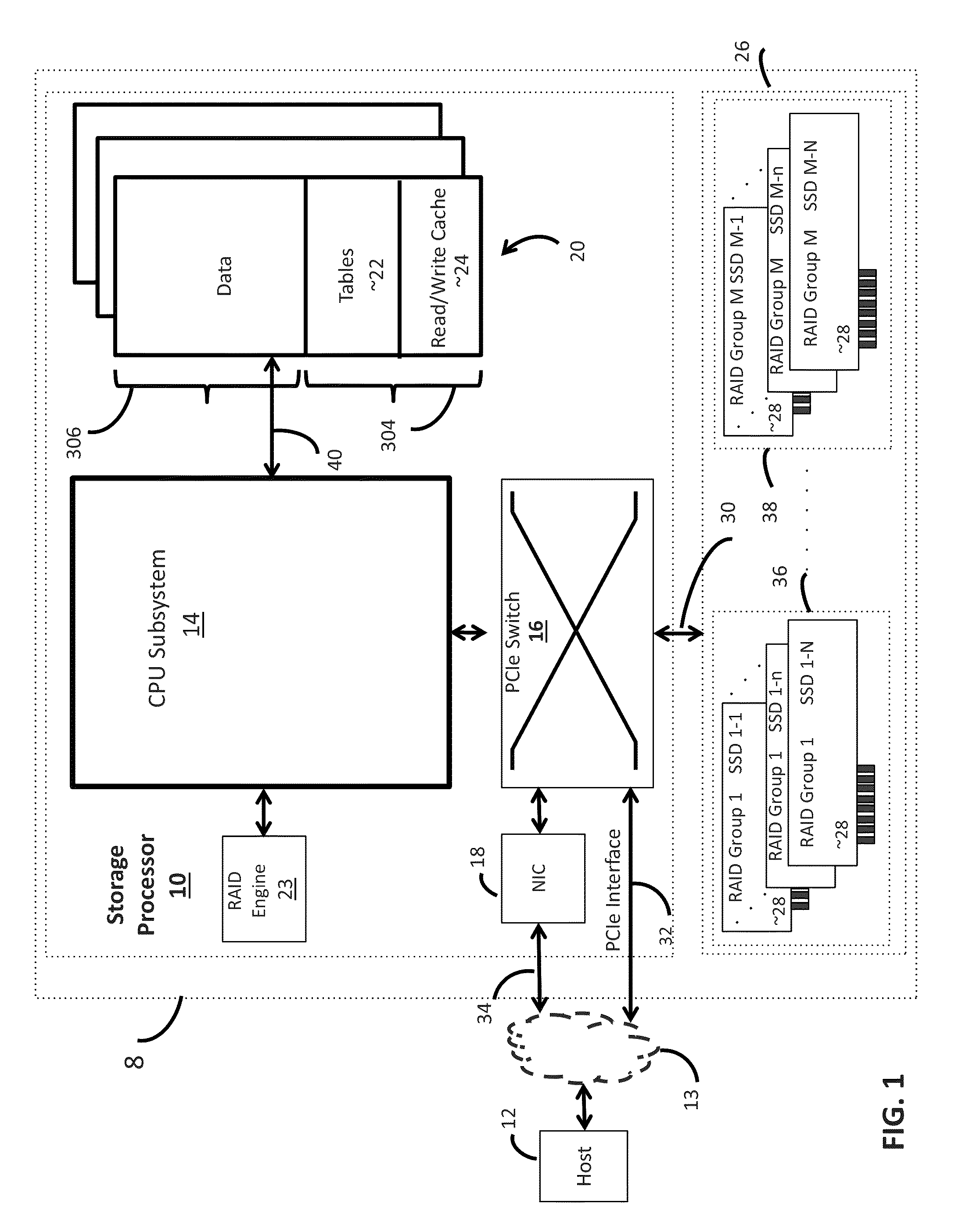
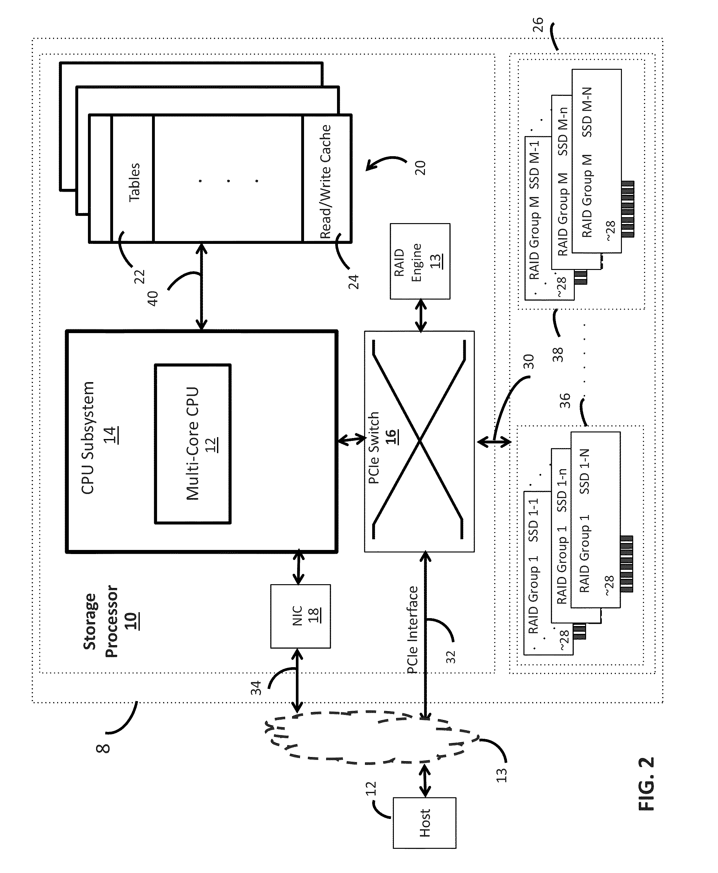
[0019]In accordance with an embodiment and method of the invention, a storage system includes one or more logically-addressable solid state disks (laSSDs), with a laSSD including at a minimum, a SSD module controller and flash subsystem.

[0020]As used herein, the term “channel” is interchangeable with the term “flash channel” and “flash bus”. As used herein, a “segment” refers to a chunk of data in the flash subsystem of the laSSD that, in an exemplary embo...

Login to view more

PUM

No PUM Login to view more

Abstract

A storage system includes a storage processor coupled to solid state disks (SSDs) and a host, the SSDs are identified by SSD logical block addresses (SLBAs). The storage processor receives a command from the host to write data to the SSDs and further receives a location within the SSDs to write the data, the location being referred to as a host LBA. The storage processor includes a central processor unit (CPU) subsystem and maintains unassigned SLBAs of a corresponding SSD. The CPU subsystem upon receiving the command to write data, generates sub-commands based on a range of host LBAs derived from the received command and further based on a granularity. At least one of the host LBAs is non-sequential relative to the remaining host LBAs. The CPU subsystem assigns the sub-commands to unassigned SLBAs by assigning each sub-command to a distinct SSD of a stripe, the host LBAs being decoupled from the SLBAs. The CPU subsystem continues to assign the sub-commands until all remaining SLBAs of the stripe are assigned, after which it calculates parity for the stripe and saves the calculated parity to one or more of the SSDs of the stripe.

Description

CROSS REFERENCE TO RELATED APPLICATIONS[0001]This application is a continuation in part of U.S. patent application Ser. No. 14 / 073,669, filed on Nov. 6, 2013, by Mehdi Asnaashari, and entitled “STORAGE PROCESSOR MANAGING SOLID STATE DISK ARRAY”, and a continuation in part of U.S. patent application Ser. No. 14 / 629,404, filed on Feb. 23, 2015, by Mehdi Asnaashari, and entitled “STORAGE PROCESSOR MANAGING NVME LOGICALLY ADDRESSED SOLID STATE DISK ARRAY”, and a continuation in part of U.S. patent application Ser. No. 14 / 595,170, filed on Jan. 12, 2015, by Mehdi Asnaashari, and entitled “STORAGE PROCESSOR MANAGING SOLID STATE DISK ARRAY”, and a continuation in part of U.S. patent application Ser. No. 13 / 858,875, filed on Apr. 8, 2013, by Siamack Nemazie, and entitled “Storage System Employing MRAM and Redundant Array of Solid State Disk”BACKGROUND[0002]Achieving high and / or consistent performance in systems such as computer servers (or servers in general) or storage servers (also known ...

Claims

Login to view more

Application Information

Patent Timeline
no application Login to view more
IPC IPC(8): G06F3/06
CPCG06F3/0619G06F3/0688G06F3/064G06F3/0616G06F3/0652G06F11/108G06F11/1096G06F12/0246G06F2211/1066G06F2212/7201G06F2212/7203G06F2212/7205
Inventor NEMAZIE, SIAMACKASNAASHARI, MEHDISHAH, RUCHIRKUMAR D.
Owner AVALANCHE TECH
Who we serve
  • R&D Engineer
  • R&D Manager
  • IP Professional
Why Eureka
  • Industry Leading Data Capabilities
  • Powerful AI technology
  • Patent DNA Extraction
Social media
Try Eureka
PatSnap group products